
Introduction
Precise flow regulation is often the difference between a stable production line and one plagued by inconsistent actuator speed, wasted air, and avoidable wear. This article examines how a flow controller throttle can be integrated into industrial pneumatic and fluid systems to improve motion control, reduce energy loss, and support more repeatable process performance. You will learn where these throttles deliver the most value, what installation and calibration factors matter most, and how they influence cycle time, efficiency, and equipment reliability. With that foundation, the discussion can move into the practical role these components play in optimizing day-to-day operations.
How Flow Controller Throttles Improve Industrial Process Performance
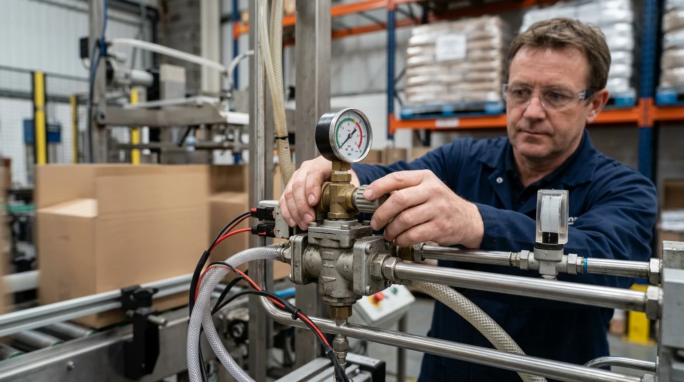
Industrial automation relies heavily on precise kinetic management to ensure that pneumatic and fluidic systems operate efficiently and safely. A highly effective method for regulating this kinetic energy is the integration of advanced flow control mechanisms. By restricting or expanding the flow path of compressed air or fluids, these devices govern the speed of pneumatic cylinders and rotary actuators. When implemented correctly, these components transform erratic mechanical movements into highly synchronized, repeatable operations.
The operational impact of upgrading to a precision-engineered flow controller throttle is highly measurable. Facilities transitioning from uncalibrated valves to specialized throttles frequently report cycle time improvements of 15% to 20%, alongside a reduction in compressed air consumption by up to 30%. These metrics underscore the critical role that flow regulation plays in overarching plant efficiency, pushing beyond simple actuation to achieve strict volumetric control.
Key performance benefits
The primary performance benefit of implementing dedicated throttling mechanismsis the stabilization of actuator speeds across varying load conditions. In standard pneumatic systems operating between 0.1 and 1.0 MPa, fluctuations in upstream pressure can cause inconsistent cylinder strokes. A properly calibrated throttle mitigates these variations by maintaining a constant flow rate, ensuring that the kinetic energy delivered to the actuator remains uniform.
Furthermore, precision throttles enhance the repeatability of automated tasks. In applications such as pick-and-place robotics, packaging machinery, or CNC tool changing, positional accuracy is heavily dependent on the velocity of the actuator. By fine-tuning the exhaust or supply air, engineers can achieve stroke timing tolerances within milliseconds, drastically reducing defect rates and mechanical wear on end-of-arm tooling.
Common process bottlenecks they solve
Industrial processes frequently suffer from bottlenecks caused by uncontrolled pneumatic energy. One of the most prevalent issues is cylinder slamming, where an actuator reaches the end of its stroke with excessive force. This not only generates disruptive noise levels but also drastically reduces the mean time between failures (MTBF) for both the cylinder and the machine frame. Throttling the exhaust air creates backpressure, providing a dampening effect that eliminates this destructive slamming.
Another common bottleneck is erratic synchronization in multi-actuator setups. When two or more cylinders must fire simultaneously to lift a heavy load or clamp a large workpiece, unequal flow rates can cause binding, jamming, or uneven pressure application. Integrating fine-tuning throttles allows maintenance personnel to balance the flow dynamically, ensuring that actuators operating under standard 0.5 to 0.7 MPa plant air pressures move in perfect unison, thereby preventing costly line stoppages and product damage.
Technical Criteria for Selecting a Flow Controller Throttle
Selecting the optimal throttle requires rigorous analysis of the system’s thermodynamic and fluid dynamic parameters. Engineers must move beyond basic port sizing to evaluate the intricate variables that dictate flow behavior under specific operational stresses. The technical criteria for selection encompass aerodynamic conductance, material resilience against corrosive media, and the degree of automation required for the specific industrial environment.
Flow range, pressure drop, and response time
The most critical specification in throttle selection is the flow coefficient (Cv), which measures the volume of fluid or gas that will pass through the valve at a specified pressure drop. Engineers must match the Cv of the throttle to the bore and stroke of the pneumatic cylinder. If the Cv is too low, the actuator will suffer from air starvation, resulting in sluggish response times exceeding 500 milliseconds. Conversely, an oversized valve compromises fine-tuning capabilities, making micro-adjustments nearly impossible.
Pressure drop (ΔP) across the throttle is another vital metric. Efficient system design aims to minimize parasitic pressure losses while maintaining control authority. High-performance throttles are engineered to provide a linear flow curve, ensuring that a 10% turn of the adjustment needle equates to a predictable percentage change in flow. Response time is equally critical in high-speed sorting applications, where automated throttles must adjust flow parameters in under 50 milliseconds to maintain synchronization with visual inspection systems.
The following table outlines standard performance thresholds for various throttle configurations:
| Throttle Type | Typical Cv Range | Max Operating Pressure (MPa) | Optimal Application |
|---|---|---|---|
| Standard Push-to-Connect | 0.1 – 0.5 | 1.0 | Light automation, packaging |
| Precision Threaded | 0.2 – 1.2 | 1.5 | High-load actuation, CNC |
| Automated Proportional | 0.5 – 2.0 | 1.2 | Closed-loop process control |
Media compatibility and material requirements
Media compatibility dictates the material composition of the throttle body, seals, and internal needle mechanisms. Standard compressed air systems, which typically operate in ambient temperatures ranging from -5°C to 60°C, generally utilize nickel-plated brass or high-strength polybutylene terephthalate (PBT). These materials offer excellent dimensional stability and resistance to the synthetic compressor oils frequently found in plant air lines.
For more demanding environments, such as chemical processing, food and beverage washdowns, or semiconductor manufacturing, material requirements become much stricter. Stainless steel (304 or 316) becomes mandatory to prevent oxidation and chemical degradation. When utilizing rigid metallic tubing for high-pressure or high-temperature media, a robust SL- compression throttle ensures a leak-free, mechanically secure connection that withstands vibration and thermal cycling better than standard polymer push-to-connect fittings.
Manual vs automated options
The choice between manual and automated throttling depends heavily on the frequency of product changeovers and the required precision of the process. Manual throttles utilize a finely threaded needle valve adjusted by hand or with a specialized tool. They are highly cost-effective and boast exceptional reliability due to their lack of electronic components. For applications where the flow rate is set once during commissioning and rarely changed, an inline SL-flow control female throttle provides a secure, tamper-resistant solution.
In contrast, automated proportional throttles integrate stepper motors or solenoids driven by analog signals (e.g., 4-20mA or 0-10V). These devices excel in flexible manufacturing environments where actuator speeds must adapt dynamically to different product recipes on the fly. While the initial capital expenditure is significantly higher, automated options eliminate the need for manual intervention, effectively reducing changeover times from minutes to milliseconds and removing human error from the calibration process.
Integrating a Flow Controller Throttle into Existing Systems
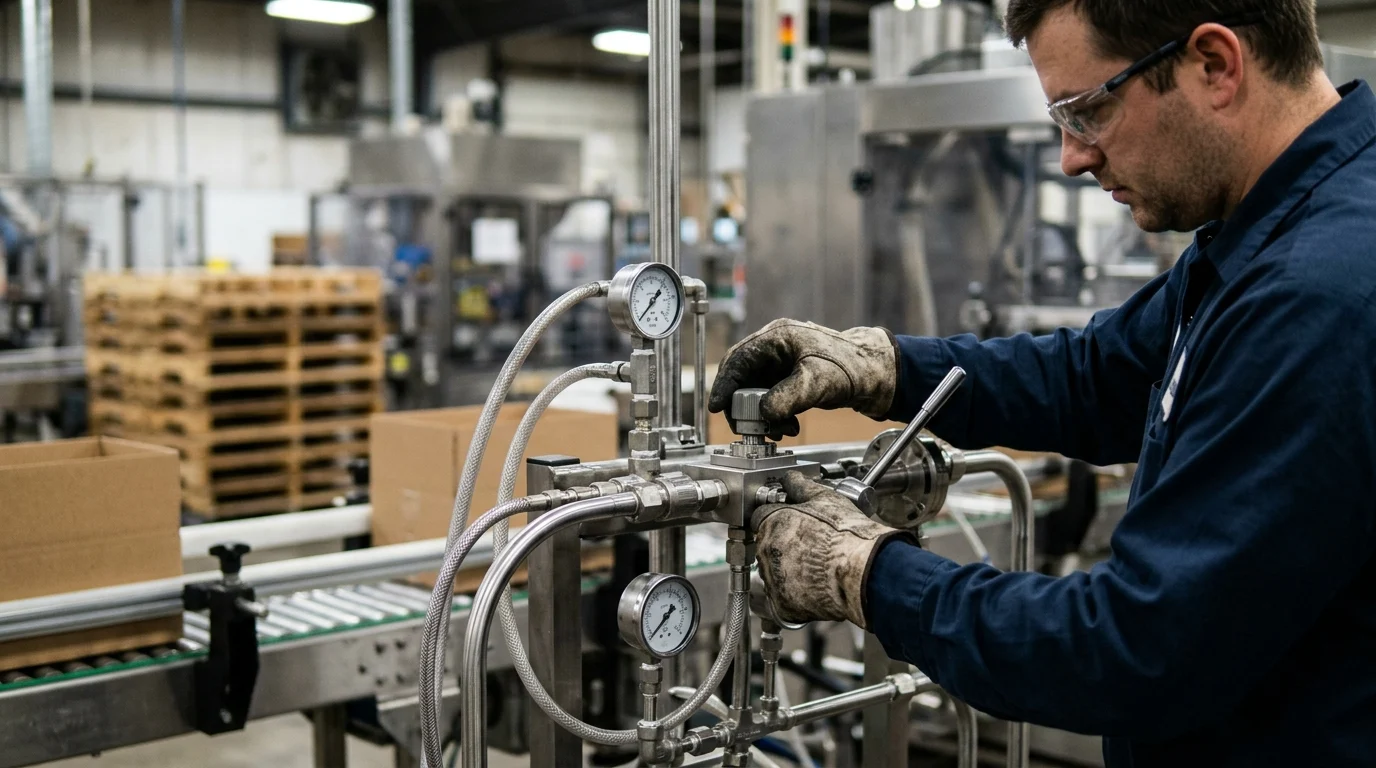
Successful integration bridges the gap between theoretical specifications and empirical performance on the factory floor. The physical installation of flow regulation devices must align seamlessly with existing pneumatic architectures, electrical control networks, and spatial constraints. Proper execution during this phase minimizes pressure drops, prevents contaminant ingress, and ensures that the system communicates effectively with central supervisory systems.
Sizing and installation steps
The first step in integration is determining whether the circuit requires meter-in or meter-out control. Meter-out control, where the exhaust air from the cylinder is restricted, is the industry standard for double-acting pneumatic cylinders. It creates a stable backpressure that prevents the actuator from lunging forward if the load suddenly shifts. Meter-in control is generally reserved for single-acting cylinders or specific fluidic applications where restricting the supply is necessary.
Once the control methodology is established, physical sizing and installation follow. Thread standards (NPT, BSPT, or Metric) must strictly match the actuator ports to prevent thread galling or micro-leaks. For rapid assembly in dense manifold environments, utilizing an SLG- flow control push on throttle accommodates standard polyurethane or nylon tubing (typically ranging from 4mm to 12mm or 1/8″ to 1/2″ O.D.). These push-to-connect designs drastically reduce installation time while maintaining a secure grip up to 1.0 MPa of pressure.
PLC, DCS, and sensor connectivity
Integrating automated flow controllers into existing Programmable Logic Controller (PLC) or Distributed Control System (DCS) architectures requires careful attention to signal processing. Most industrial proportional valves accept a standard 4-20mA analog signal, which provides excellent resistance to electromagnetic interference (EMI) over long cable runs on the factory floor. Engineers must ensure the PLC output cards possess adequate resolution—typically 12-bit or 16-bit—to leverage the micro-stepping capabilities of the throttle.
Modern Industry 4.0 integrations increasingly rely on digital fieldbus protocols such as IO-Link, PROFINET, or EtherNet/IP. These protocols allow the flow controller to transmit diagnostic data alongside its primary control function. By networking the throttles, central DCS systems can monitor real-time pressure drops, temperature fluctuations, and valve positioning. This connectivity enables predictive maintenance algorithms to flag an anomaly—such as a 5% deviation in expected flow rate—before it results in a critical process failure.
Common installation risks
Physical installation carries inherent risks that can compromise system integrity if not properly managed. Over-tightening threaded connections is a primary cause of micro-cracks in valve bodies and stripped threads in aluminum pneumatic cylinders. Technicians must adhere to strict torque specifications; for instance, an M5 thread typically requires no more than 1.5 Nm of torque, while a 1/4″ port may require 12 to 14 Nm. Utilizing liquid thread sealants instead of standard PTFE tape can also prevent fragments from shearing off and clogging the precise internal orifices of the throttle.
Contamination is another significant installation risk. Industrial environments are rife with ambient dust, machining coolant, and pipe scale. If a system is not properly flushed before the throttles are installed, particulate matter can score the needle valve or degrade the O-ring seals. Integrating a 5-micron pre-filtration unit upstream of the flow controllers is a mandatory step to protect the investment and ensure the engineered flow characteristics remain accurate over millions of cycles.
Operational, Compliance, and Cost Considerations
Beyond initial deployment, engineering teams must assess the long-term operational footprint of their flow control systems. Long-term viability is heavily dependent on lifecycle management, strict adherence to international safety standards, and a comprehensive understanding of the Total Cost of Ownership (TCO). A well-documented approach to these considerations ensures that the pneumatic infrastructure remains a reliable asset rather than a recurring maintenance liability.
Maintenance and calibration needs
Maintenance schedules for flow controllers are largely dictated by the severity of the operational environment and the quality of the compressed air supply. In clean, well-filtered systems (ISO 8573-1 Class 3 or better), high-end throttles routinely exceed a Mean Time Between Failures (MTBF) of 20 million cycles. However, the presence of moisture or degraded compressor oil can accelerate the deterioration of internal Nitrile (NBR) or Fluoroelastomer (FKM) seals, leading to internal bypass leaks.
Calibration needs vary based on the throttle type. Manual needle valves generally require periodic verification to ensure machine vibration has not caused the locking nut to back off, which could alter the flow setting. In contrast, automated proportional valves may require annual zero-point and span recalibrations to compensate for electronic drift and mechanical wear. Establishing a proactive maintenance protocol that includes ultrasonic leak detection can identify degradation long before it impacts actuator speeds.
Standards and safety requirements
Adherence to regulatory standards ensures both operational safety and legal compliance. Pneumatic systems must generally conform to ISO 4414 (Pneumatic fluid power – General rules and safety requirements for systems and their components). This standard mandates that components, including flow controllers, must safely withstand their rated pressures without catastrophic failure. Quality throttles are engineered with burst pressure ratings exceeding 1.5 MPa, providing a critical safety margin over standard 0.7 MPa operating pressures.
Material compliance is equally important, particularly for facilities operating globally. Components must comply with the Restriction of Hazardous Substances (RoHS) directive, ensuring the absence of heavy metals like lead and cadmium in the brass alloys and surface platings. Additionally, for systems deployed in the European market, the Pressure Equipment Directive (PED 2014/68/EU) may apply depending on the internal volume and maximum allowable pressure of the interconnected pneumatic circuit.
Supplier evaluation and total cost
Evaluating suppliers involves calculating the Total Cost of Ownership (TCO) rather than focusing solely on the unit purchase price. A cheaper, poorly machined throttle may save capital upfront but can cause thousands of dollars in lost yield due to inconsistent actuator speeds and frequent replacements. Engineers must evaluate suppliers based on their machining tolerances, lot-to-lot consistency, and supply chain transparency.
When assessing TCO, engineers must look beyond the hardware. The following matrix illustrates a standard 5-year TCO breakdown for a hypothetical 50-node pneumatic circuit:
| Cost Factor | Manual Inline Throttles | Automated Proportional Throttles |
|---|---|---|
| Initial Hardware Capital | $1,500 – $3,000 | $15,000 – $25,000 |
| Annual Maintenance / Calibration | $500 | $2,000 |
| Estimated Energy Savings (5 Yrs) | Baseline | -$8,500 |
| Scrap Reduction Value (5 Yrs) | Baseline | -$12,000 |
| Net 5-Year TCO Projection | $4,000 – $5,500 | $4,500 – $14,500 (varies by yield) |
This analysis demonstrates that while automated systems carry a significantly higher initial cost, their ability to reduce scrap rates and optimize air consumption can yield a competitive TCO in high-value manufacturing environments. Conversely, for standard material handling, high-quality manual throttles remain the most financially prudent choice.
How to Choose the Right Flow Controller Throttle Strategy
Finalizing a flow control strategy requires synthesizing technical specifications, integration realities, and lifecycle costs into a cohesive procurement plan. Engineering and purchasing departments must collaborate to avoid the pitfalls of both over-engineering and under-specifying. By establishing a formalized decision-making framework, organizations can standardize their pneumatic architectures, thereby reducing spare parts inventory and simplifying maintenance training.
Use-case-based decision framework
A robust decision framework maps specific application parameters against available throttle technologies. Engineers should categorize their pneumatic circuits into three distinct tiers: utility, precision, and dynamic. Utility circuits, such as basic clamps or blast nozzles, require simple, cost-effective manual throttles. Precision circuits, such as those found in automated assembly or packaging, demand high-grade threaded throttles with locking mechanisms to ensure long-term stability against vibration.
Dynamic circuits represent the highest tier, where actuator speeds must change during the machine cycle or between product recipes. These applications necessitate automated proportional valves integrated via industrial networks. By strictly defining these tiers, a facility can prevent the costly mistake of deploying a $500 proportional valve on a simple pneumatic clamp, or conversely, relying on a $5 push-to-connect fitting for a highly sensitive robotic end-effector that requires micro-metering.
Balancing cost, control, and reliability
Balancing upfront capital expenditure against long-term reliability is the ultimate goal of any industrial procurement strategy. Investing in precision-machined throttles with superior seal materials may increase initial component costs by 20% to 30%. However, this premium is rapidly offset by the reduction in machine downtime and the extension of cylinder life. In many high-throughput facilities, the return on investment (ROI) timeline for upgrading to precision throttles is typically 6 to 12 months, driven largely by a 2% to 5% reduction in product scrap rates.
Ultimately, the most successful flow control strategies are those that treat pneumatic systems not as a collection of commodity fittings, but as a highly engineered kinetic network. By rigorously applying technical criteria, ensuring pristine installation practices, and calculating true lifecycle costs, industrial facilities can achieve a level of process stability that directly enhances their competitive advantage in the marketplace.
Key Takeaways
- The most important conclusions and rationale for Flow Controller Throttle
- Specs, compliance, and risk checks worth validating before you commit
- Practical next steps and caveats readers can apply immediately
Frequently Asked Questions
What does a flow controller throttle do in a pneumatic system?
It regulates air or fluid flow to control actuator speed, reduce cylinder slamming, and improve repeatability in automated equipment.
How do I choose the right flow controller throttle size?
Match the valve’s Cv, port size, and pressure range to your cylinder bore, stroke, and target response time to avoid sluggish or unstable motion.
Should I throttle supply air or exhaust air?
For most pneumatic cylinders, throttle the exhaust air for smoother speed control and better damping at the end of stroke.
What problems can a flow controller throttle solve on production lines?
It helps fix inconsistent cylinder speed, noisy end-of-stroke impact, multi-actuator mismatch, and unnecessary compressed air waste.
Where can I find industrial flow controller throttle options from NHPC Pneumatic?
You can review flow controller throttle products and specifications directly at nhpc-pneumatic.com to compare models for your application.